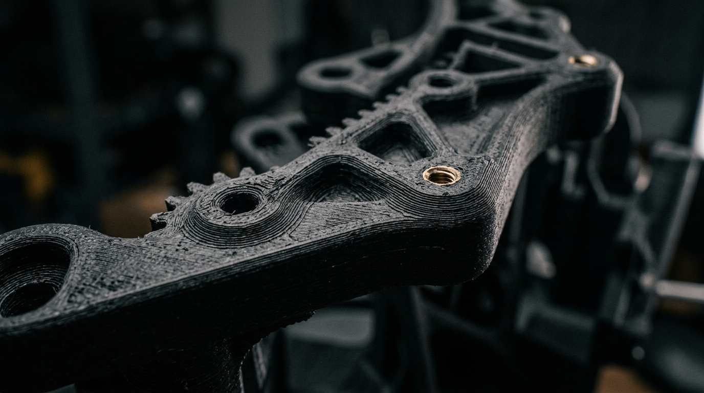
High-reliability additive manufacturing capacity for industrial applications. Replacing CNC-milled metal with high-performance carbon fiber composites (PAHT-CF). Extreme structural rigidity, ±0.05 mm tolerances, and 48-hour delivery.
Engineering Workflow & Quality
How the 3D Printing Process Works
From digital CAD model or physical sample part to fully assembled, verified carbon fiber components in 48 hours.
Step 01
Geometry & Input
Upload your CAD file (.STEP, .STL, .OBJ). Missing a 3D model or have a broken legacy part? Ship the physical component to us – we 3D-scan and reverse-engineer it parametrically in SolidWorks.
Input: CAD / Physical 3D Scan
Step 02
DfAM & Pre-Processing
Our engineers optimize the geometry for additive manufacturing. We analyze mechanical stress vectors, optimize fiber print orientation for maximum tensile strength, and select gyroid infill structures.
Tolerances: ±0.05 mm
Step 03
High-Temp Production
Printed in industrial, actively heated CoreXY chambers with 300–320°C hardened steel nozzles. Carbon-fibre reinforced polyamide (PAHT-CF / PPA-CF) and PET-CF with strong layer bonding.
Materials: PAHT-CF / PET-CF
Step 04
Post-Processing & Delivery
Installation of heat-set brass threaded inserts (M2–M8), thermal annealing for internal stress relief, and optical CMM dimensional inspection before express 48h dispatch.
Turnaround: 48h express
What We Manufacture
The practical versatility of industrial 3D printing.
Prototypes & Concepts
Test form, ergonomics, and mechanical function physically before mass manufacturing.
Replacement & Legacy Parts
Rapidly recreate discontinued, broken, or high-lead-time machine components.
Custom Jigs & Assembly Fixtures
Tailor-made, durable production tooling that streamlines your assembly line.
Electronic Enclosures
Custom-fit, heat-resistant protective housings for sensors, PCBs, and connectors.
Low-Volume Production (End-Use Parts)
Manufacture 1 to 500+ production-grade end-use composite components without tooling investment.
Hybrid Manufacturing
Investment Casting Patterns (Lost-Wax)
Beyond high-performance composites, we offer a direct bridge to pure metal. We 3D print burnout casting patterns (PolyCast/Wax) optimized for traditional Investment Casting.
The model vaporizes cleanly in a kiln without leaving ash, allowing molten metal (e.g., brass, aluminum, or steel alloys) to fill the cavity. The result is solid metal components with extreme complexity, at a fraction of the cost and lead time of conventional CNC machining or SLM metal printing.
Perfect for Racing Teams & Hypercars
Reverse-engineering obsolete spare parts
Zero tooling costs for molds
Foundry Ready
Upload your CAD file and we will deliver a wax/plastic positive ready to be handed directly to your local metal foundry.
Material library • Carbon fibre & engineering polymers
Carbon-fibre composites for tooling-grade parts.
We choose the material for the environment the part will actually work in. Our speciality is annealed high-temperature carbon-fibre composites that replace CNC machined aluminium in engine bays, industry and electronics.
Our default choice for structural metal replacement. Handles continuous use at 150°C+ with very good resistance to oil, petrol, fuels and industrial chemicals. Suited to linkage arms, engine bay brackets and structural chassis mounts.
Made for electronics enclosures, optical mounts and pressurised parts under continuous mechanical and thermal load. PET-CF absorbs very little moisture for dimensional stability (±0.05 mm), while PPS-CF is self-extinguishing (UL94 V-0) and handles harsh chemicals.
• Moisture absorption: < 0.1 % (no swelling in humid environments)
ASA & ABS (UV-resistant exterior parts & vapor smoothing)
UV- and weather-resistant polymers for outdoor use, vehicle interiors and covers. Often combined with chemical vapor smoothing for an injection-moulded look without visible layer lines.
• UV & weather resistance: very high (ASA)
• Surface finish: vapor smoothed to Ra < 1.0 μm
TPU 95A / 85A (industrial elastomers & gaskets)
Oil-resistant, hard-wearing polyurethane. Used for soft assembly jigs, vibration dampers, extraction and tool nozzles, robot grippers and custom gaskets.
• Elongation at break: > 450 %
• Abrasion resistance: very high
💡
Unsure which material fits your application?
You don't need to be a polymer specialist. Simply describe in your RFQ what environmental stress the part will face (temperature, mechanical load, fluids) and our engineers will specify the ideal material.
Post-Processing
Secondary Operations & Validation
Heat-Set Tolerance Inserts
M2–M8 brass or stainless threaded inserts installed with ultrasound or heat. High pull-out force, so panels and sensors can be mounted and removed repeatedly in composite housings.
Annealing & Curing
Stress relief in a temperature-controlled chamber for engineering plastics. Brings the polymer to its full tensile strength and heat resistance.
CMM 3D Metrology Validation
Optical scanning (heatmap) of the physical part against the nominal CAD model. We deliver an inspection report to verify the ±0.05 mm tolerance.
Laser Marking & Serialization
CO2 laser marking of QR codes, barcodes and batch serial numbers straight into the plastic for traceability.
Secure Upload & 3D Calculator
Upload your file. (STL, 3MF, OBJ, GLTF, PLY, AMF generate instant 3D visualization and pricing, other formats are sent for manual quoting). Supported formats: .STEP, .STP, .STL, .3MF, .OBJ, .PDF
Volume0.00 cm³
Estimated Price0 SEK
Note: Minimum Order Value of 500 SEK applies per order.
Design Guidelines
Design for Additive Manufacturing
Wall Thickness & Geometry
For optimal structural strength in composite prints, we recommend a minimum wall thickness of 1.2 mm. Avoid overhangs greater than 45° where possible to minimize support material.
Topology Optimization (Infill)
A solid component is rarely the strongest. By utilizing gyroid infill structures, we can reduce weight by up to 70% compared to solid aluminum, while maintaining torsional rigidity.
Insert Tolerances
For heat-pressed threaded inserts, design the pilot hole 0.1 - 0.2 mm smaller than the insert's outer diameter. Include a chamfer to guide the brass insert during assembly.
Quote
Request Technical Production
For volume production, specific tolerance requirements, or installation of brass inserts, please describe your requirements below. We reply within one working day.
Minimum Order Value: 500 SEK / ~50 EUR ex. VAT
Covers dimensional review, machine setup, thermal annealing for structural integrity, and CMM verification.